Fibre Channel Storage Networking
The SAN fabrics are built from the initiators (servers), the targets (storage systems), and the Fibre Channel switches. The SAN fabric uses the Fibre Channel Protocol as a transport, and it is the sum of the physical participants and the convergence of the processes and services of the FCP.
The initiators and the targets to connect to an FC SAN need to use specialized communication adapters designed to process the Fibre Channel Protocol. These adapters, as already mentioned, are called host bus adapters (HBAs). The HBAs process the FCP in their silicone, which provides faster and more secure communication. Figure 10-8 shows a comparison between the stack of an HBA and an NIC.

Figure 10-8 Comparison in the Stack Processing Between an Ethernet NIC and an FC HBA
The HBAs are similar to the Ethernet network interface cards (NICs) in terms of a function—both are used to provide connectivity to a network environment for the purposes of the communication. However, there is a huge difference in the way they function.
The Ethernet NICs rely on the software drivers in the operating system for protocol-related functions and processing, such as flow control, sequencing, error correction, segmentation, and others.
In comparison, the processing of the Fibre Channel Protocol stack happens in the hardware of the HBA. The SCSI protocol passes the commands to the HBA, where the FCP frames are formed and the physical connectivity is established. This takes the load off the device’s CPU and allows for better control.
The communication between the initiator and the target needs to be secure and reliable, as the FC frames carry the data, divided into blocks. It is important that the data is reassembled in the correct order at the destination of the communication and that all the blocks are present. That’s why there are multiple mechanisms and stages of FCP communication to take care of that. Figure 10-9 shows the different components of the FCP communication.

Figure 10-9 FCP Communication Components
In the FCP communication, the smallest piece of data transmitted over the FC links is called a word. The size of a word is 32 bits (4 bytes), which is serialized into 40 bits using 8-bit/10-bit encoding. The words form the FC frames. A series of FC frames sent in one direction is called a sequence, and all the sequences that form the whole conversation between an initiator and a target is called an exchange.
For clarity, here are two examples of FCP communication. The first one is a SCSI-FCP read operation, where an initiator requests data stored on the target to be read and sent to it. The second example is of a SCSI-FCP write operation, where an initiator opens communication with a target and sends data to be stored.
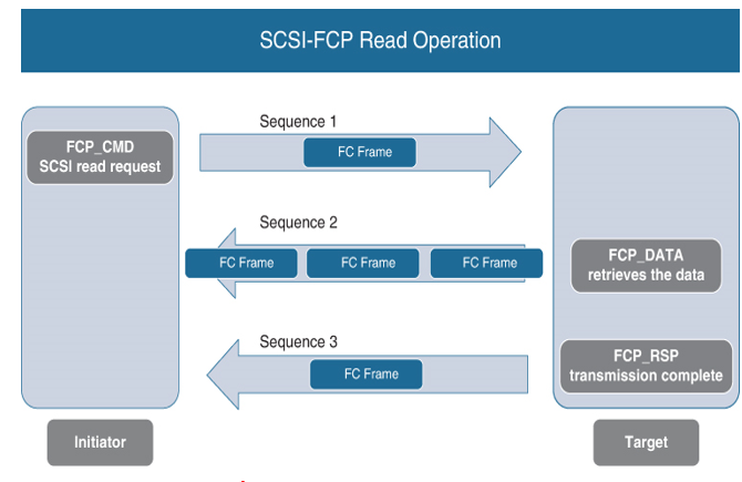
The SCSI-FCP read operation, which is illustrated in Figure 10-10, consists of the following steps:

Figure 10-10 SCSI-FCP Read Operation
Step 1. The initiator generates a SCSI read request (FCP_CMD). The server notifies the storage system that it wants to read data stored on it.
Step 2. The HBA of the initiator encapsulates the SCSI Read command into an FC frame and sends it to the target. This process is the first sequence (sequence 1) of the whole exchange.
Step 3. The target receives and processes the FC frame. It retrieves the requested data (FCP_DATA) from storage and encapsulates the data blocks in FC frames.
Step 4. The target sends the FC frames to the initiator in one sequence (sequence 2).
Step 5. The target generates a status command (FCP_RSP) that informs the initiator that the requested data transmission is complete.
Step 6. The target encapsulates the status command in an FC frame and sends it in another sequence (sequence 3).
At this point, the I/O operation is complete. The collection of all the three sequences is the entire exchange.
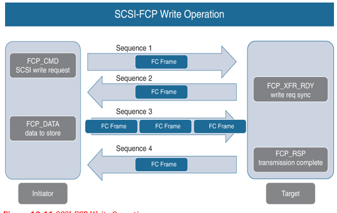
The SCSI-FCP write operation, illustrated in Figure 10-11, consists of the following steps:

Figure 10-11 SCSI-FCP Write Operation
Step 1. The initiator node generates a SCSI write request (FCP_CMD). The server will notify the storage system that it wants to send data to the storage system.
Step 2. The HBA of the initiator encapsulates the SCSI-FCP Write command in an FC frame and sends it to the target in a single sequence (sequence 1).
Step 3. The target node responds with a SCSI write request response (FCP_XFR_RDY). The write request response is required for synchronization between the initiator and target.
Step 4. The target response is encapsulated in an FC frame and sent to the initiator in another sequence (sequence 2).
Step 5. The initiator retrieves the data (FCP_DATA) from its upper-layer protocol (ULP) buffers and packages it.
Step 6. The data is encapsulated in FC frames and sent to the target in a sequence (sequence 3).
Step 7. The target generates a status command (FCP_RSP) to confirm the end of the exchange.
Step 8. The target encapsulates the status command in an FC frame and sends it as a last sequence of the communication (on the diagram this is sequence 4). All four of these sequences form the entire exchange needed to store data on a storage system.